Designing Parts for 3D Printing: Wall Thickness, Tolerances and Orientation
Buyer Guides · 18 November 2026
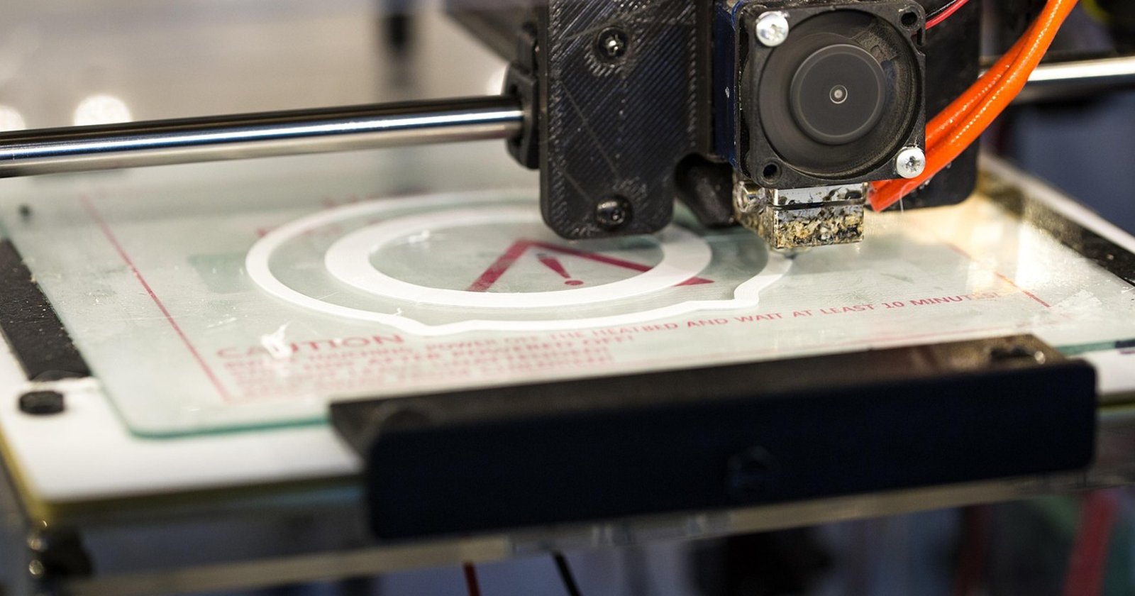
A part designed for machining or moulding will often print, but not always well. Walls that are too thin can break or distort, holes can close up, and a part printed the wrong way up can be weak in the direction that carries the load. Most of these problems are avoidable at the design stage. This guide sets out the rules of thumb for the main processes. The figures are typical ranges from published design guides. Printers, materials and settings differ, so check every figure with your supplier before you finalise the design.
Rules that apply to every process
- Wall thickness: keep walls above the process minimum, and make load-bearing walls thicker than that. Keep wall thickness as even as you can, because thick and thin sections next to each other can cool and shrink at different rates.
- Holes and gaps: small holes and narrow gaps can close up or fuse. Print them slightly oversize, or print them undersize and drill or ream them to size afterwards.
- Moving parts and fits: leave a clearance between parts that must move or fit together. The clearance needed depends on the process.
- Accuracy: printed parts are usually more accurate in the horizontal plane than in the build direction. Where a dimension is critical, tell the supplier so it can orient the part to suit.
FDM / FFF
FDM builds walls from extruded lines, so wall thickness works best as a multiple of the line width. Published guides give minimum walls of roughly 0.8 to 1 mm, with thicker walls for strength. Overhangs steeper than about 45° from vertical need supports, which leave marks where they are removed. Typical general tolerances quoted by services are around ±0.5% with a lower limit of about ±0.5 mm.
FDM parts are weakest between layers. If a part carries load, a clip flexes, or a boss takes a screw, orient it so the load runs along the layers rather than pulling them apart.
SLA and DLP (resin)
Resin printing produces fine detail and smooth surfaces. Published minimum walls range from about 0.2 mm to 0.6 mm depending on the printer and resin, but walls of 1 mm or more are more robust in use. Holes below about 0.5 mm can close during printing. Parts are printed on supports that leave small marks, so tell the supplier which faces are cosmetic. Hollow resin parts need drain holes so that uncured resin can escape.
SLS and MJF (polymer powder bed)
The surrounding powder supports the part as it builds, so overhangs and internal features need no supports. That freedom makes powder bed processes good for complex functional parts. Published minimum walls are about 0.5 to 1 mm, with around 1.5 mm or more recommended for structural walls. Hollow parts need escape holes so the unfused powder can be removed; one design guide recommends at least two holes of 5 mm or more. Quoted tolerances are typically in the region of ±0.3% with a lower limit of about ±0.3 mm, though some services quote tighter for MJF. Large flat areas and long thin sections can warp as they cool, so ribs or a slight curve can help.
Metal (laser powder bed fusion)
Metal printing builds on a plate, and surfaces at less than about 45° to the build plate usually need supports. Supports also carry heat away and hold the part in place, so the supplier will plan them. Conservative minimum walls are around 0.5 mm, with thicker sections for strength. Parts are usually stress relieved, removed from the plate, and machined on critical faces, so add machining stock to surfaces that need a tight tolerance or a fine finish, and mark them on the drawing.
Choosing the orientation
Orientation decides strength, accuracy, surface finish, support marks and often price. In processes where build height drives time, a part laid flat can print faster than one standing upright. Tell the supplier:
- Which direction the main load acts in
- Which surfaces are cosmetic and should be free of support marks
- Which dimensions are critical
- Whether the part must be watertight or airtight
With that, the supplier can pick an orientation that suits the part, or explain the trade-off.
Quick reference
| Process | Typical minimum wall | Supports | Watch for |
|---|---|---|---|
| FDM / FFF | 0.8–1 mm | Overhangs beyond about 45° | Weak between layers |
| SLA / DLP | 0.2–0.6 mm (1 mm+ for robust parts) | Yes | Drain holes, support marks |
| SLS / MJF | 0.5–1 mm (about 1.5 mm structural) | No | Powder escape holes, warping |
| Metal LPBF | About 0.5 mm | Below about 45° to the plate | Machining stock, stress relief |
All figures are typical published ranges. Check them with your supplier.
Questions to ask your supplier
- What minimum wall and hole size do you recommend for this material on your machines?
- What tolerance can you hold on my critical dimensions, and in which direction?
- How would you orient this part, and where will the support marks be?
- Do you offer a design review before printing?
- Which features would you machine or drill after printing?
Quick-reference checklist
- Keep walls above the process minimum, and thicker where they carry load
- Keep wall thickness even
- Add drain or escape holes to hollow parts
- Mark critical dimensions and cosmetic faces on the drawing
- Say which way the load acts
- Ask for a design review before the first build
Where to go for more
ISO/ASTM 52910 gives general design guidance for additive manufacturing, and ISO/ASTM 52911-1 covers design for laser powder bed fusion of metals. Our guide to SLS, MJF, SLA, FDM and metal printing explains what each process does well, and our guide to choosing a UK 3D printing service covers what to ask before you order.
Find 3D printing companies on 3DP Directory
Browse the 30 UK 3D printing companies on 3DP Directory by process: polymer powder bed (SLS and MJF), resin printing, FDM and FFF and metal 3D printing, or find help with the design itself under design and 3D scanning. Save the companies that fit to your shortlist and send one enquiry to the whole shortlist at once.
For press enquiries about 3DP Directory, contact 3dp@3dpdirectory.co.uk.
Listings related to this article

AME-3D
Dinnington, South Yorkshire
AME-3D is a 3D printing, product design and low-volume manufacturing company based at Momentum House in Dinnington, Sheffield, South Yorkshire. It runs SLA, SLS, MJF, FDM and LCD 3D printing alongside vacuum casting and RIM moulding, with an in-house design team offering CAD design, design for manufacture and reverse engineering. Materials include PA11 and PA12 nylon, glass-filled nylon, TPU, ABS, PETG and PLA, and parts can be sanded, primed, painted, dyed, bead blasted or vapour smoothed. The company is ISO 9001:2015 certified and works with automotive, medical, aerospace, defence, subsea, consumer product, film and TV and industrial customers.
- SLA
- SLS
- MJF
- FDM/FFF

Apex Additive Technologies
Ebbw Vale, Blaenau Gwent
Apex Additive Technologies is a metal additive manufacturer in Ebbw Vale, Blaenau Gwent, producing parts by laser powder bed fusion (LPBF) on Renishaw single-laser and multi-laser systems. Materials include Ti6Al4V Grade 23 titanium, AlSi10Mg aluminium, IN718 and IN625 nickel alloys, 316L stainless steel and M300 maraging steel. Supporting services include process and application development, vacuum heat treatment, wire EDM, and 3D scanning and reverse engineering with a blue-laser scanner and 7-axis measuring arm. The company serves aerospace and defence, medical (including cranio-maxillofacial implants), oil and gas, automotive, tooling and consumer goods customers.
- Metal LPBF/DMLS
- 3D Scanning
- Reverse Engineering
- DfAM Support

CREAT3D
Wokingham, Berkshire
CREAT3D is an additive manufacturing specialist in Wokingham, Berkshire, running an in-house 3D printing bureau alongside 3D printer supply, training and support. Through its LayerParts platform it produces nylon parts in PA12 and PA66 by SLS, from one-off prototypes to small batch production, with all manufacturing kept in-house. Contract manufacturing covers design optimisation, CAD, finishing and assembly, with shot blasting, part polishing and dyeing available. Applications engineers help with material selection, optimising parts for additive production and scheduled production slots. Customers include aerospace, automotive, defence and general manufacturing companies.
- SLS
- Design/CAD
- DfAM Support

Croft Additive Manufacturing
Warrington, Cheshire
Croft Additive Manufacturing is a metal 3D printing business in Risley, Warrington, producing complex components by selective laser melting in 316L stainless steel. It supports design for additive manufacturing, multi-part to single-part redesign, lightweighting and reverse engineering, and supplies prototypes and low-volume production runs. Croft AM is a sister company of Croft Filters, drawing on more than 30 years of engineering experience, and has supplied parts for filtration, tooling and a space mission. Sectors served include aerospace, automotive, marine, medical instruments, motorsport and oil, gas and energy.
- Metal LPBF/DMLS
- DfAM Support
- Reverse Engineering

Midlands 3D Printing
Stone, Staffordshire
Midlands 3D Printing is a 3D print manufacturer in Stone, Staffordshire, running HP Multi Jet Fusion production around the clock alongside a large FDM print farm, industrial FFF, SLS TPU and SLA. Materials range from PA11 and PA12 nylon, TPU, PETG and ABS to PEEK and ULTEM, with DeepDye colouring, vapour smoothing, painting, threaded inserts and PPAP inspection available in-house. The company holds ISO 9001, ISO 14001 and Cyber Essentials Plus certification, is JOSCAR registered, and supplies prototypes through to batch production for automotive, motorsport, defence, healthcare, marine, consumer products and media customers.
- MJF
- SLS
- FDM/FFF
- SLA

Rapid Fusion
Exeter, Devon
Rapid Fusion is a large-format additive manufacturing company in Clyst Honiton, Exeter, that builds its own robotic printing systems and offers large-format 3D printing as a service on its Apollo, Zeus and Medusa platforms. Build sizes reach 2.5m x 2.5m, with integrated CNC milling for finishing to ±0.1mm. Materials include the Dahltram range of carbon and glass fibre reinforced polymers, including PC-blend and PEI grades rated to 204°C. Services cover rapid prototypes with 48–72 hour turnaround, composite moulds, jigs and fixtures, and DfAM design optimisation for aerospace, defence, automotive, construction and marine customers.
- Large-Format Printing
- CNC Machining
- DfAM Support
- Design/CAD

SGD 3D
Nottingham, Nottinghamshire
SGD 3D is a 3D printing service in Bulwell, Nottingham, Nottinghamshire, producing FDM, SLA and SLS parts for prototypes and low-volume production. Materials include glass-filled PA12 nylon on SLS, Formlabs standard and engineering resins, and FDM materials from PLA, PETG, ABS, ASA and TPU to polycarbonate, ULTEM and PEEK, including fire-retardant grades. The company holds ISO 9001 certification and offers CAD design, 3D scanning, reverse engineering, vapour smoothing and first article inspection reports for aerospace, defence, automotive, rail and industrial customers.
- FDM/FFF
- SLA
- SLS
- Design/CAD